Download PDF Manual:
PA micro electric rope hoist instructions.pdf
Full Text of Manual:
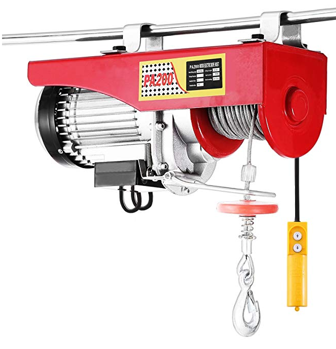
INSTRUCTIONS
Thank you for purchasing the mini electric hoist in
our company, We hope it can bring the convenience in you need
Please ~ead and_ understand this manual carefully before you
make the tnstallation and operation of mini electric hoist.
especially the “SAFE OPERATION” and to ensure everyone who use
the mini electric hoist before to read and understand this part.
TECHNICAL PARAMETERS FORM
capa Lifting Uftng Cable qu
Model usage Work duty Rated
city speed
SAFE OPERATION PROCEDURES
please follow this procedures and notice the safety
when you use the mini electric hoist: ·
I .’Pleaseread and understand this manual carefully bef- ore
you apply the mini electric hoist. The installation location Mini
electric hoist must be chosen to meet the needs and to facilitate
the operation . We must check regularly the installation of microelectric
hoist and confirm it is solid or not.
2. The capacity of the mini electric hoist is limited, pleasedorlt
overloading use .And don’t use it when you don’t know the weight
of the objects (including hanging pull buried stowage, cables,
inclined condole)! Overloading might damage the mini electric
hoist or the rope, and also increase unsafe factors of the operation
process . We suggest to use the pulley to operate when you hook
clog, this method can make the load to reduce by50%.
3.Mini electric hoist is designed according 3-20% ( 25% )lOmin(
namely it works 2min and need have to rest 8min) Please
don’t long time use continuous. Using continuous may increases
unsafe factors during operating: seriously will damage the motor.
4.Please don’t”pull”suspendedobjects when the mini electric
hoist was working, otherwise. it will increases load of the mini
electric hoist, and made mini-electric hoist and wire rope in
overloading condition.
5.Kecp mini electric hoist working area clean and tidy.Don’t
let other personnel near and contact taut wire rope, forbid anyone
standing on the below in operation state of mini electric hoist.
6.As the need tochange the wire rope, its type specification
must be consistent with the original wire rope
?.Please put thick leather gloves on and don’t allow wire rope
fro~ your hand across when Wire rope in working. otherwise the
lesaons of wire rope might stab your hand .
8.At the end of the operating please put w re rope inb canister
and do not use hand directly to lead and array wire rope. ·
. 9: Do not use hooks hook rope itself, do not use micro-rope
hoist he,
-2-
r
hitch the ob.,ic:ct suspended, otherwise it win damage trcvokcd. he
rope. so p”leasc use other appropriate rope to hitch the object
10. Limit device is as a safety device configuration, it can
make sure when hook rose to limit position be shut off when
I I .Don’t use mini electric hoist hook someone or use for
manned elevator. this mini electric hoist is not to be used lifting.
12.Mini electric hoist installation positions must be sure the
warning sign and tell1ale marks in striking state, because we need
13. Ensure the operation of micro -electric hoist to operate
without any barrier · · ·
14.please do not operation Mini electric hoist In drinking,
15.Pleasc don’t below th~ mini electrit hoist afounu when it.
works.
16. Please use thefixed attachment of the mini electric hoist
provided, or you are insecure.
r, F; =’1
17. Don’t optional re~onstrucl o·r· welimini electric hoist
18. With • the mini: elect.r,ic,. ~oi!it .~ook o,~Jcc t, make sure rope .
cylinder on retained for alleast 3 laps wire rope, in orderto
prevent the wire rope is too stress ftom rope cylinder on shedding.
INSTALLA 1 ION
Warning: Qpen box. Be sure to op<;n and take paper tape
wrapped around the rope drum, orily after that can test mach!nc, if
rush.to test machines, may caus~ r~.p,e rewind and crash aircraft. .
The location ofrri.ni-electric hoist installation is according
to operational 11eeds. Be proposed to install in a special bracket
for mini-electric hoist. and should. be solid and reliable.
othert~~~·rt av_oid wire rope_ wtth aqd limit rack direct contact
electric hoist istlnJo c , awuoser kJhe hmtt switch failure, causing mi cro: ing properly
soak~~i~0w~oernotht let th
. . • e pro cct1on c ass of m1cro-elecfnc hoist IP40
w Mm, e~ectric hoist needs to use the fixed hex bolts. flat
ashers. spnng washers etc. ensure proper installation of all
compo~~nts, an~ tighten “bolts with torque wrench, enclosed
anne~ 1nstallat10n. map. Ensure that the fixed ring (or other
substitute) firmly press the mounting pole (round rod or square
bar). so as the micro-electric hoist body not to move or rotate
Power installation
Mini electric hoist the standard of work is. s_ingle-phasc a~
power source 220V 150 (Hz), and must be used contain grounding
Warning: ensure all cables and mini electric hoist on rotational or
fever parts maintain proper distance.
OPERATION
switch
Not to operate the switch, “rising switch”, falling switch”
in “disconnect” form, “urgent stop switch” (only for PAIOOO) in
•”make up” slate, mini electric hoist motor power d.isconnected,
mini electric hoist in braking. Press the “rising switch” (near cable
side). the “rising switch” in the “make up” condition, mini electric
hoist motor rises loop the power is connected, mini electric hoist
is in motion state. At the same time hook is rising status. Click
“falling switch” , “falling switch” in the “make up”
condition,, mini electrk h isl motor decline loop the power
is connec!ed r”lini el~1,;tr1c b” ::.. :s an motion state.and hook falling
sta te.
-4-